1.1
- What is a serial link?
A serial
link connecting 2 devices is made up of an external bus (which is
the cable), that connects 2 specialized processors which are called
UART and are included in each communicating device. The cable is installed
between the 2 device connectors.
The bus
of the standard serial link (RS232 type) consists of a minimum of
2 wire (2 lines), TX for Transmission and RX for Reception. On this
support, the UART processors exchange bytes in a data flow. The bytes
are converted into a sucession of bits (and conversely) (Remember
a byte is made of 8 bits). The bits correspond to the 0 and 1 logic,
this is converted into 2 levels of voltage on the bus. These bits
make the data bytes to be exchanged.
A serial
link may also use other lines to make the data flow control easier.
The transmission speed, the byte format and the exchanged control
bits are setable in the UART. For example, to communicate with an
Atari floppy drive, the speed should be 19200 bauds (19200 bits per
one second), there is no parity and there is one stop bit for byte
flow control.
Theoretically,
that's all: after the adjustment of these parameters, bytes can be
exchanged on a serial link.
But this
is not so simple in our application (serial communication between
the PC and the Atari floppy disk), because the Atari serial link has
a little more features and differ a bit, giving a better reliability.
1.2
- The Atari Serial Link: difference between the PC end Atari RS232 signals
The UART
processor of the Atari computer is included in the POKEY processor.
The bits
are produced by POKEY with 2 different levels of voltage. These voltage
levels are in the TTL standard format on the Atari side (0VDC for
logic 0 and +5DVC for logic 1). But on the PC side, these level are
fully RS232C compliant (i.e. voltage is between -10 and +10VDC for
the logical 0 and 1).
It
is thus necessary to set up an interfacing
circuit in order to convert
these levels of tension and to make them compatible and identical.
The Atari
computer is connected to all its peripherals through a same serial
link chain. This connection link is done by the Atari serial cable
(with 13 pins connector).
Each
Atari pheripherical device has its own label, its own identification
number on the serial connection chain, we will call this number the
slave number (term of use in the serial link communication).
This
number is partly accessible, for example for the Atari disk drives,
it may be adjusted from $31 to $34, by setting a switch in the back
of the disk drive. There could be then 4 different floppy disk drives
for one Atari computer.
1.3
- The Atari serial link connector: a non-standard connector
Let's
examine the Atari serial cable and its connectors which have 13 pins
(the cable has 13 wires + ground). The description follows:
| PIN |
NAME |
Description |
| 1 |
BIDIRECTIONAL
CLOCK |
BIDIRECTIONAL CLOCK INPUT SIGNAL LINE |
| 2 |
SERIAL
CLOCK OUT |
CLOCK
OUTPUT SIGNAL LINE |
| 3 |
DATA
IN |
DATA
INPUT SIGNAL LINE |
| 4 |
GND |
GROUND
0V |
| 5 |
DATA
OUT |
DATA
OUTPUT SIGNAL LINE |
| 6 |
GND |
GROUND
0V |
| 7 |
COMMAND |
COMMAND
SIGNAL LINE |
| 8 |
MOTOR
ON |
TAPE
MOTOR SWITCH ON |
| 9 |
PROCEED |
PROCEED SIGNAL LINE |
| 10 |
+5VDC
READY |
READY
SIGNAL LINE (+5VDC) |
| 11 |
AUDIO
IN |
AUDIO
INPUT SIGNAL LINE |
| 12
(*) |
+12
VDC |
+12
VDC |
| 13 |
INTERRUPT |
INTERRUPT
SIGNAL LINE |
(*)
Non connected / not used on Atari XL/XE
CLOCK
IN, CLOCK OUT, PROCEED, INTERRRUPT:
are
normally not used in standard for data storage to data disque and
to data tape.
[Information about these signals will be available soon]
MOTOR
ON, AUDIO IN:
are
normally used with the Atari Tape device.
DATA
IN et DATA OUT :
correspond
to the 2 ''standard'' RX and TX lines, i.e. the line for data receiving
and the line for data sending (transmitting).
+5VDC/READY:
with
this signal, the Atari computer shows its presence in a ready status
(operating condition state), to all its connected slave peripherals
(which are listening), by putting +5VDC/READY the line
to +5VDC.
To
communicate with an Atari disk drive, a +5VDC on the +5VDC/READY
line must thus be generated. This voltage is normally provided
by the Atari computer. If we want to connect the Atari disk drive
to our PC (the PC replacing then the Atari computer), the PC must
provide this voltage.
However
this voltage is not available on the PC RS232C
serial connector series,
thus an external power supply must be set up.
COMMAND:
When
the Atari computer wants comunicate with one of its peripherals,
it first sends a TTL level signal towards its slave, meaning that
it is going to send a command (request). The COMMAND line
is used to carry this signal. Then the Atari computer sends a command
frame (succession of byte) on the serial link, to all the connected
and ready slaves, by using the DATED OUT (TX) line.
All
the slave peripherals read then the message, but only one will answer,
the one whose slave ID number corresponds to the one coded in the
command frame.
To
communicate with an Atari disk drive, it is thus necessary to handle
the COMMAND signal on the COMMAND line.
If
we want to connect the Atari disk drive to the PC, the PC replacing
the Atari computer, a serial link signal of the PC must be used
to generate the signal COMMAND.
We
will use, for example, the PC serial RTS signal, which will be also
converted into a compatible TTL-level signal by the interface circuit,
for interfacing the Atari disk drive.
1.4
- The Protocol: frame of command bytes and frame of data bytes:
Just
like the bytes of the command frame are not taken randomly, it is
important to understand what are the bytes to be sent or received.
It is necessary to understand how does the data exchange process run,
this mean to know all about the data exchange protocol.
This
protocol corresponds to a ''software layer'' in opposition to the
physical layer (hardware) which are the connector, the cable, the
electrical signals. This protocol is characteristic of each communicating
device. It is the common language, it must be the same one for 2 connected
devices.
For Atari,
this protocol is easy to understand, it consists of an exchange of
command bytes, of data bytes and of control bytes. It's a talking
between the requesting master (the Atari computer) and the slave (the
peripheral device), and schematically, that gives the following:
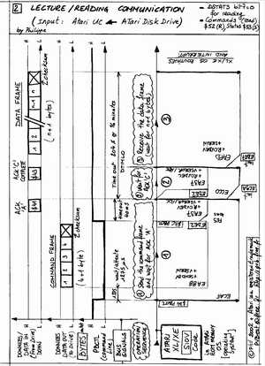
For
a data reading:
|
Device
|
Byte type
|
''Translation''
|
|
ATARI COMPUTER |
Command |
Disk drive number one, I want to read sector 10! |
|
DRIVE n°1 |
Control |
OK command WELL RECEIVED! |
|
- |
- |
(the floppy disk starts to turn, then the disk drive reads sector
10) |
|
DRIVE n°1 |
Control |
OK DONE, the sector is ready to be sent to computer! |
|
DRIVE n°1 |
Data |
Send data on the serial bus |
|
DRIVE n°1 |
Control |
Send last byte of checksum |
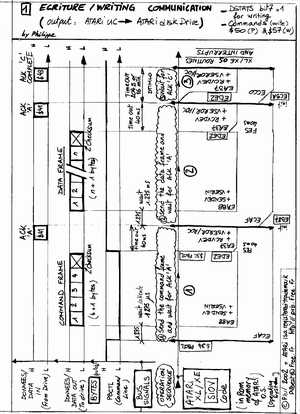
For
a data writing:
|
Device
|
Byte type
|
''Translation''
|
| ATARI COMPUTER |
Command |
Disk drive number one, I want to write data onto sector 10! |
| DRIVE n°1 |
Control |
OK command WELL RECEIVED, I am ready to receive the data! |
| ATARI COMPUTER |
Data |
Send data on the bus series |
| ATARI COMPUTER |
Control |
Send last byte of checksum |
| DRIVE n°1 |
Control |
OK data WELL RECEIVED! |
| - |
- |
(the floppy disk starts to turn, then the disk drive writes sector
10) |
| DRIVE n°1 |
Control |
OK data well written, over! |
This
protocol is included in a software code program, which reacts and
gives the bytes required for the data exchange. On the Atari, this
code is found in the ROM read-only memory of the Atari computer OS
(Operating System) and in the peripheral device OS.
For our
PC application, il is quite simple to code this protocol in a PC software
written in C++ for example, rather than trying to modify the protocol
by recoding the Atari disk drive OS, which is anyway impossible!
1.5
- Command frame details:
Sequentially,
the Atari computer sends the command frame (for the request) first,
because it is the master. This command frame is made of 5 bytes, which
are in the sending order:
- 1st
byte: the peripheral device slave number (printer, tape, floppy
disk drive #1...),
- 2nd
byte: the command to carry out (reading, wrtiting, formating...)
- 3rd
et 4th bytes: auxiliary parameters (like the sector number).
- 5th
byte: the checksum. This value is the sum modulo 256 of the 4 first
bytes.
1.6 - The control bytes:
Normally,
the peripheral slave device must answer to a command frame with an
ACK (acknowledge) byte. Generally the control bytes are sent by the
Atari peripheral device according to the progress of the commnucation
process. These control bytes are named: ACK, CPL, ERR and NAK.
| Control |
eq.
Char/Hexa |
Name |
Description |
| ACK |
'A'
/ $41 |
ACKNOLEDGE |
OK
WELL RECEIVED! |
| NAK |
'N'
/ $4E |
NON
ACKNOLEDGE |
NOT
RECEIVED ! |
| CPL |
'C'
/ $43 |
COMPLETE |
OK
DONE! |
| ERR |
'E'
/ $45 |
ERROR |
ERROR! |
1.7
- The checksum:
The command
frame and the data frame include a last byte for the checksum. This
checksum value (one byte) is the modulo 256 sum of all the frame data
bytes which have just been sent.
1.8
- The communication error code returned by the disk drive:
- NAK:
error #139 ($8B) on the Atari computer. Generally appears when
the Atari computer asks the disk drive for a non-existant sector or
when the disk drive does not contain any floppy disk.
- ERR:
error #144 ($90) on the Atari computer. Generally appears when
the Atari disk drive has not managed to read the sector (bad sector)
or when the floppy disk is write-protected.
1.9
- Other error that the Atari computer Operating System may return:
- Erreur
#143 ($8F) Checksum error. In fact, the Atari computer calculates
the checksum of the data byte frame received. It compares then this
value with the one sent by the peripheral device at the end of the
frame. If the checksums are different, it means that there was an
error in the communication process and data flow.
- Erreur
#140 ($8C) Error on byte frame input on the serial port (Serial
Data Input Frame Error).
- Erreur
#142 ($8E) Over-run error while reading on the serial port (Serial
Data Input Over-run).
- Erreur
#138 ($8A)
Answer time is over on the serial port, time out error (Serial Data
Input Time-Out).
(Non-exhaustive
list)
For
the interface cable and circuit realisation click here.